Categories

The U-Section Flanged Butterfly Valve Install on Pipe

Unlike a wafer valve that is merely "sandwiched" between flanges, the U-section flanged butterfly valve uses captive nuts housed inside the valve body's U-slot to engage fully threaded stud bolts. This allows the valve to be securely clamped to either pipe flange independently — delivering true dead-end service where one side of the pipeline can be disconnected while the other remains pressurized.
Aug 5th,2026 9 Views

Introduction

Installing a butterfly valve correctly is the difference between decades of leak-free service and a recurring maintenance headache. Among butterfly valve body styles, the U-section flanged design stands apart for its clever bolting arrangement: the body contains a U-shaped slot with captive nuts that grab fully threaded stud bolts from either pipe flange. This article explains the installation principle in detail — how the captive nut U-slot works, why it enables independent flange clamping and dead-end service, and how to torque the joint correctly for a reliable, leak-tight connection.

1. Anatomy of the U-Section Flanged Butterfly Valve

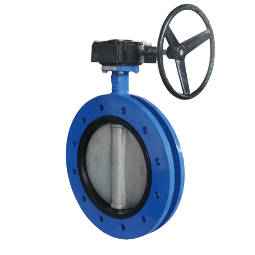
The U-section flanged butterfly valve takes its name from the U-shaped slot machined around the body's outer circumference. This slot is not just a weight-saving groove — it is the mechanical heart of the bolting system:
1.1 The U-Slot and Captive Nuts

  • U-shaped channel — A continuous groove machined around the valve body at the flange pitch circle diameter.
  • Captive nuts — Nuts are housed (retained) inside the U-slot, aligned with each flange bolt hole position. The slot walls hold the nuts captive so they cannot rotate or fall out when the stud bolt is threaded in.
  • Full circular coverage — The number of captive nuts matches the flange bolt count    (e.g., 12 captive nuts for a DN300 PN16 flange with 12 bolt holes).


1.2 Fully Threaded Stud Bolts

Installation uses fully threaded stud bolts (also called all-thread studs) rather than partially threaded bolts. Full threading is essential because:

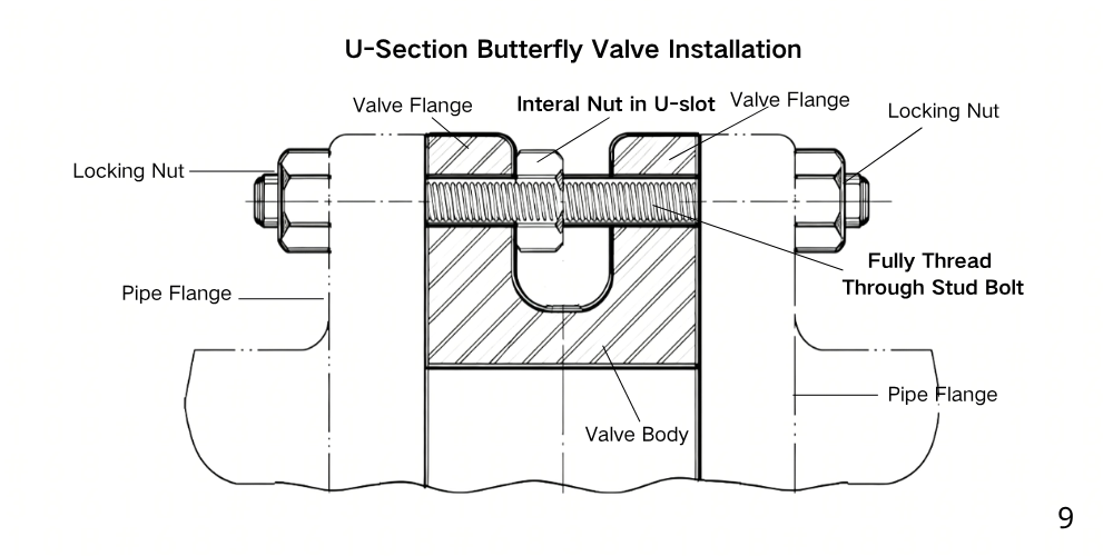
  • The stud passes through the entire flange-to-flange assembly, engaging the captive nut in the middle and locking nuts at both outer ends.
  • Full thread engagement distributes the clamping load evenly along the joint.
  • Thread engagement depth into the captive nut determines the maximum clamping force the joint can sustain.

2. How the Valve Clamps to Each Flange Independently

The genius of the captive nut U-slot design is that each pipe flange is clamped independently. Here is the step-by-step mechanism:
  1. Insert the stud — A fully threaded stud bolt is inserted through the bolt hole of the first pipe flange.
  2. Engage the captive nut — The stud is threaded into the captive nut housed in the valve body's U-slot. The stud now "grabs" the valve body through the nut.
  3. Tighten the locking nut — A locking nut is threaded onto the outer end of the stud against the pipe flange face. Tightening this nut pulls the flange against the valve body face, compressing the integral rubber liner gasket.
  4. Repeat for the second flange — The same process is repeated on the opposite side. Because each side has its own set of studs, captive nuts, and locking nuts, the two flanges are clamped to the valve completely independently.


3. Why Independent Flange Clamping Matters: Dead-End Service

Independent clamping is what gives the U-section flanged valve its most valuable capability: dead-end service.

What is Dead-End Service?

Dead-end service means the valve can hold full rated pressure on one side while the opposite side of the pipeline is disconnected, blanked off, or open to atmosphere. This is essential for:

  • Isolation during maintenance — Remove a downstream pump or piece of equipment while the upstream line stays pressurized and in service.
  • End-of-line termination — Install the valve at the end of a pipeline, bolted to the last flange with nothing beyond it.
  • Blind flange blanking — Bolt a blind flange directly onto one valve face for safe isolation.

Why Wafer Valves Cannot Do This

In contrast, a wafer valve is held in place only by the compression of long studs spanning both flanges. If one flange is removed, the wafer valve has nothing supporting it — it drops out of alignment and cannot hold pressure. The U-section captive nut design eliminates this limitation because each flange is bolted independently to the valve body.

4. Locking Nuts and Clamping Force: Creating a Leak-Tight Joint

The reliability of the connection depends on the clamping force developed at both ends of each stud bolt:

4.1 How the Clamping Force Is Created

  • Inner end — The stud engages the captive nut in the U-slot, anchoring the valve body.
  • Outer end — The locking nut is tightened against the pipe flange face. As the locking nut is torqued, the flange is drawn toward the valve body face, compressing the integral rubber liner (which acts as the flange gasket).
  • Result — The controlled compression of the rubber liner between the flange face and the valve body face creates a reliable, leak-tight seal.

4.2 Recommended Torque Procedure

  1. Align — Position the valve between the flanges with the disc 10-15% open (never fully closed during installation).
  2. Insert all studs — Thread all studs through both flanges into their captive nuts by hand.
  3. Snug — Tighten all locking nuts by hand to seat the rubber liner evenly.
  4. Star pattern, 3 passes — Using a calibrated torque wrench, tighten in a crisscross (star) sequence at 30%, then 60%, then 100% of final torque.
  5. Verify disc clearance — Rotate the valve fully open and closed to confirm the disc clears the pipe bore.
  6. Re-torque after 24h — Recheck torque after thermal cycling or 24 hours of service; rubber liner may relax slightly.

4.3 Torque Values (Typical Guidance)

Valve Size Stud Size Recommended Torque Notes
DN50-DN100 M16 35-50 Nm Lower range for small flanges
DN125-DN200 M16-M20 50-90 Nm Verify per material
DN250-DN300 M20-M24 90-140 Nm Larger flange = higher torque
DN350-DN600 M24-M30 140-220 Nm Always confirm with datasheet

Note: Torque values are typical guidance. Always use the exact torque specified on the valve datasheet for your specific size, pressure class, and seat material. Over-torquing can crush the rubber liner; under-torquing causes leaks.

5. Installation Best Practices and Common Mistakes

Best Practices

  • Install with the disc 10-15% open to avoid pinching the rubber seat.
  • Use fully threaded studs of the correct grade (typically 8.8 or B7) for full thread engagement with the captive nut.
  • Clean flange faces and stud threads; apply light thread lubricant to achieve accurate torque readings.
  • Support the valve before tightening so its weight does not distort the joint.
  • Use a calibrated torque wrench and a star-pattern sequence in three passes.

Common Mistakes

  • Partially threaded bolts — Do not engage the captive nut properly and reduce clamping capacity.
  • Tightening one side fully first — Can distort the valve body; alternate sides progressively.
  • Disc fully closed during installation — Pinches and tears the rubber seat when the flanges are drawn together.
  • Adding external gaskets on rubber-faced valves — The rubber liner is the gasket; adding another one reduces sealing integrity.
  • Skipping the 24-hour re-torque — Rubber relaxes slightly after initial compression; re-torquing maintains the clamp.

6. U-Section vs Wafer Installation — Quick Comparison

I
U-Section Flanged Valve Wafer Valve
Bolting Method Stud bolts + captive nuts in U-slot Long studs through both flanges
Flange Connection Each flange independent Both flanges interdependent
Dead-End Service Yes (full rated pressure) No
Centering Self-centering via stud alignment Manual, prone to misalignment
Flange Removal Either side removable independently Removal breaks valve support
Relative Cost $$ (Higher) $ (Lower)

Frequently Asked Questions

Q: What is a captive nut and why is it used in U-section valves?

A: A captive nut is a nut retained inside the U-shaped slot of the valve body, aligned with each flange bolt hole. It cannot rotate or fall out. When a fully threaded stud bolt is inserted through the pipe flange and threaded into the captive nut, the valve body is anchored to that flange. This allows each flange to be clamped independently.

Q: Can I disconnect one pipe flange while the line is pressurized?

A: The valve is designed for dead-end service within its rated pressure. You can disconnect the downstream flange while the upstream side remains pressurized, provided the valve is closed and the pressure is within the valve's rated limit. Always follow site safety procedures and depressurize where practical.

Q: Can I use ordinary hex bolts instead of fully threaded studs?

A: No. Ordinary bolts do not have threads on both ends to engage the captive nut and receive an outer locking nut. Fully threaded stud bolts are required for the U-section captive nut system to work correctly.

Q: Do I still need external gaskets?

A: No. The U-section valve's rubber liner extends beyond the body faces and serves as the integral flange gasket. Adding external gaskets can actually reduce sealing integrity. External gaskets are only needed for metal-seated or high-performance U-section valves with bare metal faces.

Q: How do I know when the clamping force is correct?

A: Use a calibrated torque wrench at the values in the valve datasheet, applied in a star pattern in three passes (30%/60%/100%). Verify the rubber liner is compressed evenly around the full circumference. Re-torque after 24 hours of service.

Q: Can a U-section valve be used at the end of a pipeline?

A: Yes. The independent flange clamping allows end-of-line installation. A blind flange can be bolted directly onto the free valve face for safe isolation at the rated pressure.

Conclusion

The U-section flanged butterfly valve's captive nut U-slot and fully threaded stud bolt system solve a problem that wafer valves cannot: independent flange clamping and true dead-end service. By anchoring the valve to each flange separately, it stays securely in place even when one side of the pipeline is disconnected, while maintaining a reliable, leak-tight joint through controlled clamping force from the locking nuts on both ends.

For installation drawings, torque datasheets, or project-specific guidance, contact the Laux Valve technical team.

Contact Laux Valve:
Email: james@lauxvalve.com | Tel/WhatsApp: +86 18920833829

Learn more about our butterfly valve products, manufacturing standards, customization options, and technical support.

What types of butterfly valves do you manufacture?

We manufacture a complete range of industrial butterfly valves, including wafer butterfly valves, lug butterfly valves, U-section butterfly valves, double flange butterfly valves (AWWA C504), grooved end butterfly valves, PTFE lined butterfly valves, and double eccentric butterfly valves.

Do you provide OEM and customized butterfly valves?

Yes. We offer OEM and ODM services, including customized dimensions, materials, coatings, branding, and packaging to meet different project requirements and international standards.

Which industries use your butterfly valves?

Our butterfly valves are widely used in water treatment, wastewater, chemical processing, petrochemical, HVAC, marine, mining, and municipal pipeline systems.

Which international standards do your butterfly valves comply with?

Our products are manufactured according to ISO, CE, API, ANSI, DIN, BS, JIS, and AWWA C504 standards, depending on customer and project requirements.

How do you ensure butterfly valve quality?

Every butterfly valve undergoes strict material inspection, pressure testing, leakage testing, and dimensional inspection before shipment to ensure reliable performance and long service life.

How can I get a quotation?

Simply send us your valve specifications, or project requirements. Our engineering and sales team will provide a quotation, technical support, and the most suitable butterfly valve solution within 12 hours.

Why choose Laux Valve as your butterfly valve manufacturer?

With over 15 years of manufacturing experience, ISO 9001 & CE certification, advanced production facilities, and global export expertise, Laux Valve provides reliable butterfly valve solutions supported by professional engineering and responsive customer service.

We use Cookie to improve your online experience. By continuing browsing this website, we assume you agree our use of Cookie.