A butterfly valve is only as reliable as the condition it leaves the factory in. Even a correctly designed valve can arrive on site with coating damage, a misaligned disc, an incomplete bolt hole pattern, a scratched seat, or an actuator that was never tested with the valve. A structured pre-shipment inspection catches these problems before they become installation delays, leak failures, or warranty claims.
This guide explains how to inspect a resilient seated or high-performance butterfly valve before it is packed and shipped. It covers documentation, visual inspection, dimensions, seat and disc condition, shaft sealing, operation testing, pressure testing, coating, accessories, marking, and final packing. Use it as a factory inspection checklist or as a receiving inspection checklist when the valve arrives at your warehouse or project site.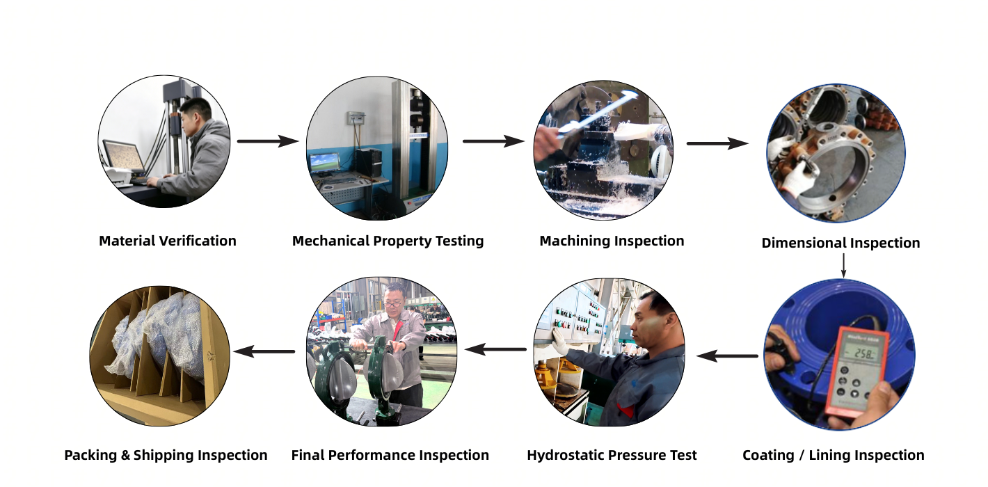
Pre-shipment inspection is the last opportunity to correct a problem while the valve is still at the manufacturer’s facility. After shipment, a missing test report, incorrect flange drilling, or damaged seat is much more expensive to resolve because the valve must be returned, repaired on site, or rejected after the construction schedule has already been committed.
For distributors, EPC contractors, and plant owners, a documented inspection is also evidence of quality control. It supports material traceability, proves that the valve was tested before dispatch, and reduces the chance that a site problem is blamed on the manufacturer without evidence.
Inspection should always be performed against three references: the purchase order, the approved valve drawing or data sheet, and the applicable standard such as API 609, EN 593, AWWA C504, ISO 5211, EN 12266-1, or the project specification. Do not inspect from memory or from a generic valve description.
Start with paperwork because a dimensional or material error found on paper is faster to correct than one found on the valve. Confirm the following documents are available and match each other:
Before measuring anything, inspect the complete valve in good light. Look for damage that can occur during casting, machining, coating, assembly, or handling.
Pay particular attention to the disc in the partially open position. The edge that contacts the seat should be smooth and free of coating lumps, weld spatter, or machining marks. Any defect on this line can cause a seat leak even when the rest of the valve passes.
Dimensional inspection confirms that the valve can actually be installed in the mating pipe or between the mating flanges. For each valve size and body style, check the following against the approved drawing:
| Dimension | What to Verify | Why It Matters |
|---|---|---|
| Face-to-face / structural length | Match the applicable standard, such as API 609, EN 558, ISO 5752, or AWWA C504. | A valve that is too long cannot fit between existing flanges or into a compact skid. |
| Flange or lug bolt circle | Match the flange drilling standard, bolt circle diameter, and bolt hole orientation. | Incorrect drilling prevents installation or forces field modification. |
| Number and size of bolt holes | Verify every hole is drilled through and the quantity matches the standard. | Missing or undersized holes cause bolting failure or schedule delay. |
| Flange face type | Flat face, raised face, or groove end as ordered. | A flat-face valve mated to a raised-face flange can crack or leak. |
| Bore / inside diameter | Confirm the port size and any liner, seat, or disc clearances. | An undersized bore increases pressure drop and may block the disc. |
| Top flange | Match the ISO 5211 flange size, bolt circle, and drive square dimensions. | A wrong top flange prevents actuator mounting or creates side load on the stem. |
| Stem extension length | Confirm exposed stem, keyway, and coupling dimensions. | Actuator coupling and buried-service extensions must fit exactly. |
For wafer, lug, and double flange valves, the connection style must be checked differently. A wafer valve is clamped between pipe flanges, a lug valve bolts directly to each flange and can be used for dead-end service, and a double flange valve has a full body with drilled flanges on both ends. Review the exact requirements in our wafer vs lug vs double flange butterfly valve guide.
The seat and disc are the valve’s primary sealing pair. Inspect them together, with the disc moved through the full stroke so that the entire sealing edge is visible.
Rotate the disc slowly while looking at the seat-to-disc contact. If the contact line shifts to one side or if the disc rubs unevenly, the disc may be misaligned, the stem may be bent, or the seat may be installed incorrectly.
The shaft system carries the disc, transmits actuator torque, and seals the valve against leakage to atmosphere. Inspect the upper and lower shaft areas carefully.
For material selection background, see the butterfly valve stem materials comparison and the complete butterfly valve materials breakdown.
Every valve should be operated through at least one complete open-close-open cycle before shipment. For gear-operated and actuated valves, test the complete assembly, not only the bare valve.
| Check | Pass Condition |
|---|---|
| Full open position | Disc reaches the fully open position without forcing; position indicator agrees with the actual disc angle. |
| Full closed position | Disc seats fully and smoothly; no spring-back, binding, or metallic interference. |
| Travel stops | Open and closed stops are set correctly and do not allow over-travel that could damage the seat or disc. |
| Gear operator | Handwheel or lever turns smoothly, with no unusual noise, looseness, or excessive backlash. |
| Position indicator | Pointer or indicator aligns with the true disc position and is visible from the operating side. |
| Lockout or memory stop | Where supplied, the locking device engages and holds the valve in the required position. |
Do not accept a valve that only opens partway because of interference between the disc and the body, seat, or liner. If operating torque is higher than expected, investigate before shipping rather than assuming the actuator will overcome it. See the guide to reducing butterfly valve operating torque.
Butterfly valves are normally hydrostatically or pneumatically tested before shipment. As a buyer or inspector, verify the test report and witness the test if the order requires it.
Important: do not confuse a pressure test report for the wrong size or model with the valve being inspected. The serial number on the report must match the serial number on the valve nameplate. For more on leakage diagnosis after installation, see why your butterfly valve is leaking.
Internal and external coating protects the body and disc from corrosion. A coating that looks acceptable can still be too thin, poorly bonded, or contain pinholes that expose bare metal.
Coating is not cosmetic. In waterworks, buried, marine, and chemical service, a pinhole can start localized corrosion that eventually damages the valve body or contaminates the process.
When the valve is shipped with an actuator, the factory should treat the valve and actuator as one assembly. Verify the mechanical interface, wiring, setting, and accessories together.
If the valve and actuator are packed separately, mark the pair clearly and include an assembly drawing so the site team installs them in the correct orientation.
The final step is to confirm that the valve will survive handling and arrive in the same condition it left the factory.
| Inspection Item | Result |
|---|---|
| Purchase order, drawing, data sheet, and nameplate match | Pass / Fail / N/A |
| Material test certificates are complete and traceable | Pass / Fail / N/A |
| Pressure test report is present and serial number matches | Pass / Fail / N/A |
| Body and disc have no visible casting, machining, or handling damage | Pass / Fail / N/A |
| Seat is clean, undamaged, and correctly bonded or retained | Pass / Fail / N/A |
| Face-to-face, flange drilling, and top flange dimensions match the drawing | Pass / Fail / N/A |
| Stem rotates smoothly and is properly retained | Pass / Fail / N/A |
| Valve opens and closes fully; stops and position indicator are correct | Pass / Fail / N/A |
| Coating DFT and holiday test meet specification | Pass / Fail / N/A |
| Actuator interface, travel settings, and accessories are correct | Pass / Fail / N/A |
| Flange faces and ports are protected; disc is in the correct shipping position | Pass / Fail / N/A |
| Valve is correctly crated, marked, and secured for transport | Pass / Fail / N/A |
| Defect | Likely Cause | Required Action |
|---|---|---|
| Seat cut or flattened at one point | Disc misalignment, handling damage, or foreign object | Replace or re-bond the seat; realign the disc |
| Flange hole pattern does not match drawing | Wrong pattern or wrong body machined | Reject or re-machine if permitted by design |
| Coating overspray on seat or stem area | Poor masking before coating | Clean the machined surfaces and reinspect |
| Disc does not reach fully open position | Actuator stop, coupling setting, or body interference | Correct travel setting and re-test |
| High or inconsistent operating torque | Seat friction, bearing damage, stem bend, or debris | Find and correct the cause before shipment |
| Stem has excessive radial play | Worn or missing bushing, incorrect machining | Replace bushing and recheck shaft alignment |
| Nameplate or serial number missing | Assembly or documentation error | Replace nameplate and update traceability records |
Start by comparing the purchase order, approved drawing, data sheet, nameplate, and test reports. If those documents do not all describe the same valve, the remaining dimensional and visual checks are unreliable. Then inspect the body, seat, disc edge, stem, flange drilling, and coating in that order.
You do not always have to witness the test, but the test report must be traceable to the valve serial number. For critical, high-pressure, fire-safe, or high-value valves, a witnessed test is strongly recommended. Confirm the test medium, pressure, duration, acceptance criteria, and test standard before the test begins.
No. Resilient seated butterfly valves are usually shipped slightly open so the disc does not compress the seat continuously during transport and storage. A fully closed position can cause permanent seat set and may lead to leakage after installation. Confirm the manufacturer’s recommended shipping position.
Open the disc until the full sealing edge is visible and use clean, dry, non-abrasive gloves. Look for cuts, blisters, embedded debris, separation, and permanent compression marks. Do not use sharp tools to probe the seat, and do not leave the valve open against a dirty or wet surface that could contaminate the sealing area.
The most common defects are incorrect flange drilling, coating overspray on the seat or stem area, damaged or misaligned disc edges, incomplete test documentation, incorrect actuator travel settings, and stem binding from bushing or coupling problems. A detailed checklist catches most of these at the factory rather than on site.
Yes. The same checklist can be used as a receiving inspection. However, factory inspection is faster to correct and provides stronger traceability because the valve has not yet been shipped, handled, or stored. For large orders, use a pre-shipment inspection plus a shorter receiving inspection.
The applicable standard depends on the valve design and application. Common references include API 609 for industrial butterfly valves, EN 593 for European valve design, ISO 5211 for actuator mounting, EN 12266-1 or API 598 for testing, and AWWA C504 for waterworks butterfly valves. The purchase order and approved data sheet take precedence when they are more specific.
At a minimum, request the packing list, dimensional drawing, material test certificates, pressure test report, coating report, and installation and maintenance instructions. Additional documents may include NSF/ANSI 61 approval, fire-safe test report, fugitive emission test report, calibration certificates, and actuator wiring or setting records.
Contact LAUX Valve to arrange a pre-shipment inspection or to receive a complete inspection and test plan for your butterfly valve order.
Disclaimer: This article is for general engineering reference. Inspection criteria, test pressures, acceptance limits, and document requirements must be confirmed against the project specification, applicable standards, and the manufacturer’s certified data sheet for the selected valve size, pressure class, body style, and trim.
With over 15 years of manufacturing experience, ISO 9001 & CE certification, advanced production facilities, and global export expertise, Laux Valve provides reliable butterfly valve solutions supported by professional engineering and responsive customer service.